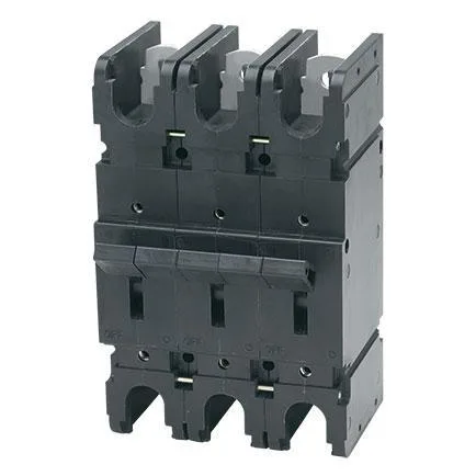
In today’s applications, ambient operating temperatures present circuit protection challenges for many design engineers. High current thermal protective devices may not provide the desired degree of protection.
The JLE/JRE Series magnetic hydraulic circuit protector addresses this issue by providing circuit protection for high current applications with a consistent trip point over temperatures ranging from –40°C to +85°C. The JLE/JRE Series is actually a family of circuit protectors available in one to six-pole assemblies with a variety of configurations and terminal styles. The principal member of this family is the JLE, an F-frame “listed circuit breaker” which complies with conditions of UL-489.
Other members of the family include the JTE, for telecommunication applications and comply to UL-489A, and the JAE, a special construction version. In addition, the JAE is now in compliance with the standards used in Australia and New Zealand, AS 60947.2-2005 (equivalent to IEC 60947-2:2006+A1). The JAE/JRE/JLE series magnetic-hydraulic circuit protector provides circuit protection for high current applications. It provides a consistent trip point over temperatures ranging from –40°C to +85°C.
Features
- Mid-trip handle available for visual identification of fault-tripped circuit breakers
- Optional internal low voltage shunt to meter current (single and multi-pole units are dimensionally equivalent in depth)
- Terminal options for design flexibility in various applications
- Multiple trip time delays for application flexibility
- Electrical and mechanical actuated auxiliary switch options for external monitoring of circuits
- Reduced voltage drop through the circuit breaker vs. other circuit protective devices
Part Numbers
Specifications
Nominal DCR / Impedance
Current Ratings
(Amps) | Resistance (ohms) |
| DC Delays |
| 51, 52, 53 |
| 100 | .000375 |
| 110 | .000375 |
| 125 | .000340 |
| 150 | .000325 |
| 175 | .000315 |
| 200 | .000225 |
| 225 | .000225 |
| 250 | .000225 |
| 400 | .000125 |
| 600 | .000083 |
| 800 | .000063 |
| 1,000 | .000050 |
| 1,200 | .000042 |
Notes: Resistance is plus or minus 50%. If a metering shunt option is provided it will add the shunts resistance to these values (i.e. A 400 Amp metering shunt would add (R=V/I). 0000625 Ohms of resistance to the non-metering shunt value of .000125 Ohms or .0001875 Ohms for a 400 Amp unit with a metering shunt). DC resistance values are based on measurements by the voltmeter ammeter method. Rated current applied for one hour and at a voltage not less than 20 volts. |
Recommended Torque Specs
| Component | Torque (in-lbs) |
| 10-32 Mounting Inserts | 10 to 12 |
| M5 Mounting Inserts | 8 to 10 |
| 3/8-16 and M10 x 1.5 Captive Nuts | 220 to 230 |
| 3/8-16 and M10 x 1.5 Studs | 220 to 230 |
| Solderless Connectors | 180 |
Approximate Weight Per Pole